TL;DR:
- Network topology influences data flow, failure cascades, and scalability in modern enterprise environments. Practitioners often overlook the divergence between physical and logical topologies, which are critical for security and troubleshooting. Hybrid designs combining multiple topology types provide optimal balance in cost, fault tolerance, and scalability.
Network topology defines more than where cables run. It determines how data moves, where failures cascade, and whether your infrastructure can scale without a full redesign. Despite this, the network topology types explained in most textbooks stop at the physical layer, leaving practitioners underprepared for the realities of modern enterprise environments where logical and hybrid topologies dominate. This article covers every major topology type in detail, contrasts their trade-offs, and connects theory directly to infrastructure planning decisions you will actually face.
Table of Contents
- Key takeaways
- Core network topology types explained
- Comparing topology trade-offs
- Physical vs logical topology
- Choosing the right topology
- My perspective on topology planning in practice
- Plan your network with Re-solution
- FAQ
Key takeaways
| Point | Details |
|---|---|
| Physical vs logical distinction | Physical topology describes cabling; logical topology governs data flow and may differ significantly from the physical layout. |
| Hybrid topologies dominate enterprise | Modern enterprise networks combine star, tree, and mesh elements to balance cost, redundancy, and scalability. |
| Mesh complexity scales fast | A full mesh of n nodes requires n(n-1)/2 links, making partial mesh the practical choice at scale. |
| Topology affects fault tolerance directly | Star topologies isolate device failures; bus and ring designs let a single fault disrupt the entire segment. |
| SDN changes logical topology dynamically | Software-defined networking separates the control plane from hardware, allowing logical topology to change without physical recabling. |
Core network topology types explained
Understanding network topology starts with recognising that each type represents a deliberate structural decision, not simply a diagram in a textbook. The seven foundational types each carry distinct trade-offs across cost, resilience, and maintenance overhead.
Point-to-point
The simplest structure: one direct link between two nodes. Common in WAN connections, leased lines, and dedicated server-to-server links. Latency is predictable and throughput is consistent, but there is no redundancy. A single link failure isolates both endpoints entirely.
Bus topology
All devices share a single communication channel. Data transmitted by any node travels the full length of the bus, and every device receives it. Bus topology was prevalent in early Ethernet (10BASE2 coaxial) but is rarely deployed in new installations. A cable fault or termination failure takes down every connected device simultaneously, making fault isolation exceptionally difficult.
Ring topology
Devices connect in a closed loop. Data travels in one direction (or both in dual-ring configurations such as FDDI) until it reaches its destination. Ring topology offers predictable latency because each frame traverses a known number of hops. The weakness is the same as bus: a break anywhere in the ring disrupts the entire loop unless a self-healing protocol is in place.
Star topology
Every device connects to a central switch or hub. Star topology is the most common choice for office LANs because a single device failure affects only that device, fault isolation is straightforward, and adding new nodes requires only an available switch port. The central switch becomes a single point of failure, which is why enterprise deployments use redundant switches with failover protocols such as RSTP or VSS.
Tree topology
Tree topology is a hierarchical extension of star, with multiple star segments connected through intermediate switches or distribution layers. It is the dominant model in campus and enterprise LANs, typically expressed as the three-tier access-distribution-core model. Data centre architects have increasingly moved toward leaf-spine architectures, a flattened two-tier variant of tree topology, specifically to reduce east-west latency for cloud workloads.
Mesh topology
Every node connects to every other node (full mesh) or to a subset of nodes (partial mesh). Full mesh delivers maximum redundancy: there is no single point of failure, and traffic can reroute around any failed link instantly. The cost is significant. A full mesh of n nodes requires n(n-1)/2 links, meaning a 10-node mesh needs 45 connections. Partial mesh is the practical compromise in most WAN designs and data centre interconnects, providing redundancy on critical paths without the full link overhead.
Hybrid topology
Hybrid topologies combine two or more of the above structures to meet specific requirements. A university campus might use a tree topology for its access and distribution layers, full mesh between core switches, and point-to-point links for off-site connectivity. Modern enterprise networks most commonly deploy hybrid topologies precisely because no single model addresses every requirement for scalability, fault tolerance, and cost simultaneously.
Pro Tip: When documenting a hybrid topology, map each segment by its dominant type. This makes it far easier to isolate faults and communicate design intent to third-party engineers during audits or incidents.
Comparing topology trade-offs
Choosing between topology types requires a structured comparison across the factors that matter most in production environments. The table below summarises the key characteristics of each type.
| Topology | Fault tolerance | Scalability | Relative cost | Maintenance complexity |
|---|---|---|---|---|
| Point-to-point | Low (no redundancy) | Very low | Low | Very low |
| Bus | Very low | Low | Very low | High (fault isolation is poor) |
| Ring | Low to moderate | Moderate | Low | Moderate |
| Star | Moderate | High | Moderate | Low |
| Tree | Moderate to high | High | Moderate | Moderate |
| Mesh (full) | Very high | Low to moderate | Very high | High |
| Mesh (partial) | High | Moderate | Moderate to high | Moderate |
| Hybrid | High | Very high | Variable | High |
The table confirms what practitioners already know anecdotally: balancing cost, scalability, and fault tolerance requires compromise. Star offers the best cost-to-manageability ratio for most office environments. Mesh delivers unmatched redundancy for critical interconnects but demands significant investment. Hybrid designs allow targeted investment, placing high-redundancy segments only where the business case justifies it.
Hybrid topologies also mitigate the weaknesses of their component types. Adding a redundant core switch pair to a tree design converts the core layer into a partial mesh, eliminating the single point of failure without rebuilding the entire access layer. This is precisely why hybrid topologies are predominant in modern enterprise environments.
Pro Tip: Do not choose a topology based on budget alone. A bus or ring deployment may appear cheap at installation, but the operational cost of fault isolation and downtime risk will exceed the savings within a short period.
Physical vs logical topology
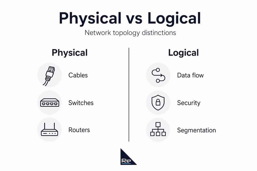
Physical topology describes the actual arrangement of cables, switches, routers, and access points in a building or campus. Logical topology describes how data actually flows through that infrastructure. These two views often diverge significantly in production networks, and conflating them is one of the most common sources of design and troubleshooting errors.

Consider a star-wired physical layout where every workstation connects to a central switch. If that switch runs VLANs, the logical topology segments traffic into isolated broadcast domains. The physical star remains unchanged, but the logical view now resembles multiple independent networks sharing the same hardware.
Here is how to distinguish and document both views accurately:
- Document physical topology first. Record every physical link, its media type, length, and endpoint. This is your ground truth for cabling faults and hardware replacements.
- Layer logical topology on top. Map VLANs, routing adjacencies, VPN tunnels, and any overlay networks. Note where logical paths cross physical boundaries.
- Identify where they diverge. A VPN tunnel may appear as a direct logical connection between two remote sites even though the physical path traverses multiple ISP hops. This divergence matters enormously for latency analysis and security policy enforcement.
- Account for SDN overlays. SDN and VPNs create logical overlays independent of physical cabling, meaning logical topology can change through software configuration without touching a single cable.
- Update both views after changes. Infrastructure changes such as new VLANs, SD-WAN policies, or firewall zones alter the logical topology even when no physical work occurs.
The logical topology governs security and compliance considerations more directly than physical topology in most contemporary networks. Segmentation policies, Zero Trust enforcement zones, and NAC boundary definitions all live in the logical layer. Getting this view wrong has direct security implications, not just operational ones.
Software-defined networking takes this separation further. Platforms built on SD-WAN principles decouple the control plane entirely from the physical hardware, allowing network architects to redefine logical paths, policies, and segmentation through a centralised controller without recabling. A useful overview of emerging network architecture trends illustrates how this is reshaping design expectations for 2025 and beyond.
One frequently overlooked example of physical-versus-logical divergence is Active Directory site topology. Errors in site topology inputs cause some of the most common and difficult-to-diagnose AD replication issues. AD computes replication paths from subnet-to-site mappings provided by the administrator. When those mappings are inaccurate or over-granular, AD replication performance degrades even though the physical network is perfectly functional. The logical model fed into AD is the problem, not the hardware.
Choosing the right topology
Selecting a topology for a real deployment involves more than matching a diagram to a use case. The following factors should drive the decision:
- Network size and growth trajectory. Star and tree topologies scale well as device counts increase. Bus and ring topologies become progressively harder to manage. If growth plans are unclear, design for the upper estimate.
- Criticality and uptime requirements. Applications with zero tolerance for downtime, such as trading platforms, manufacturing control systems, or emergency services, justify the cost of partial or full mesh on critical paths.
- Traffic patterns. North-south traffic (client to server) suits traditional tree designs. East-west traffic (server to server), common in virtualised data centres and containerised workloads, favours leaf-spine or mesh architectures.
- Budget and operational resource. Mesh and hybrid designs require more skilled engineers to manage. Factor in operational cost alongside capital expenditure.
- Existing infrastructure. Incremental redesign is often more realistic than a full replacement. Identify the segments with the highest fault risk and prioritise redundancy there first.
Pro Tip: Avoid over-engineering. A well-implemented star or tree topology with redundant switches and documented failover procedures outperforms a poorly managed partial mesh every time. Complexity is only worth the investment when the operational team has the skills to maintain it.
Effective network visibility requires multiple abstraction levels: topological diagrams, health metrics, and execution traces. Relying on a single diagram gives an incomplete picture of how your network actually behaves under load. Use topology documentation tools alongside monitoring platforms to maintain an accurate, current view.
A well-structured network infrastructure planning process will formalise these decisions before deployment begins, reducing costly rework and ensuring the chosen topology aligns with both current needs and future growth.
My perspective on topology planning in practice
I have reviewed a significant number of network designs over the years, and the pattern I keep encountering is this: organisations spend time classifying their topology and almost no time questioning whether the classification matches what is actually deployed. The physical diagram says star. The monitoring data tells a different story.
The traditional rigid classification of topologies has become less practical with modern hybrid and software-defined networks. In my experience, the engineers who design the most resilient networks are the ones who think in terms of traffic flows and failure scenarios first, and then let the topology label follow from those decisions, not the other way around.
What I have found most valuable is treating the logical topology as the primary design document. The physical layer changes slowly. The logical layer changes constantly, with every new VLAN, VPN policy, or SDN rule. If your documentation does not keep pace with logical changes, your troubleshooting will always lag behind your incidents.
The advice I give consistently is this: build topology documentation into your change management process, not as an afterthought. Every change ticket should include a logical topology update. It sounds like overhead until the first major outage when accurate documentation cuts your mean time to resolution by half.
— Jacob
Plan your network with Re-solution
Understanding the theory of network topologies is the starting point. Translating that understanding into a production-grade design that meets your organisation’s specific requirements for performance, resilience, and security is where the real work begins.

Re-solution brings over 35 years of Cisco infrastructure expertise to that process. Whether you are planning a campus network refresh, migrating to a Network as a Service model, or need an independent audit of your existing topology, Re-solution’s engineering team can assess your current infrastructure and recommend a topology and architecture aligned to your operational needs. Explore the full scope of IT infrastructure solutions Re-solution offers, or review common infrastructure challenges to identify where your current design may be falling short.
FAQ
What are the main types of network topology?
The seven core types are point-to-point, bus, ring, star, tree, mesh (full or partial), and hybrid. Most modern enterprise networks use hybrid topologies that combine elements of star, tree, and mesh.
What is the difference between physical and logical topology?
Physical topology describes the actual cabling and hardware arrangement. Logical topology describes how data flows through that infrastructure. Technologies such as VLANs, VPNs, and SDN overlays mean the two frequently differ.
Which network topology offers the highest fault tolerance?
Full mesh topology offers the highest fault tolerance because every node has a direct connection to every other node, eliminating single points of failure. The trade-off is significant cost and complexity, as the number of required links scales as n(n-1)/2.
Why do most enterprise networks use hybrid topologies?
Hybrid topologies allow architects to combine the cost-efficiency of star and tree structures with the redundancy of mesh on critical paths. This flexibility makes them the predominant choice for organisations with complex, multi-site requirements.
How does SDN affect network topology?
Software-defined networking decouples the control plane from physical hardware, allowing logical topology to be reconfigured through software without physical changes. This makes logical topology far more dynamic and separates it further from the physical layer.
Recommended
- Network Infrastructure Planning Simplified | Re-Solution
- Network Infrastructure Planning Simplified | Re-Solution
- IT Infrastructure Explained Simply | Re-Solution