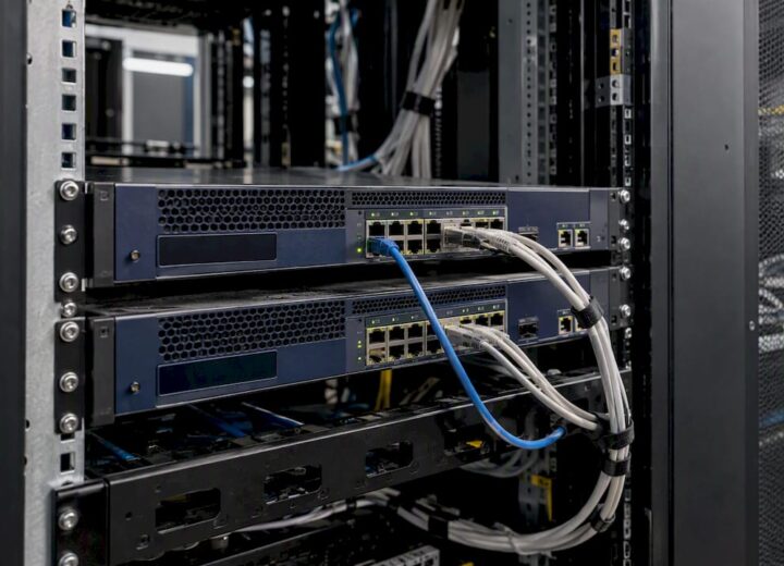
A network switch forwards Ethernet frames between devices on the same LAN by learning MAC addresses and sending traffic only where it needs to go. That single function underpins almost every wired network in existence, from a small office with a handful of PCs to a university campus with thousands of connected devices. Understanding how network switch working principles operate gives you a reliable mental model for both troubleshooting and procurement.
A switch is the right device when you need to:
- Expand the number of wired ports beyond what a router provides
- Reduce unnecessary broadcast traffic compared with a hub
- Segment traffic logically using VLANs
- Power devices such as access points or IP cameras via PoE
Table of Contents
- What a network switch does and how it fits into your LAN
- How network switch working mechanics actually function
- What types of switches exist and which features matter
- How VLANs segment your network traffic
- How to connect a switch to a router correctly
- How to tell if a network switch is working properly
- How to choose the right switch for your environment
- When to choose a managed service and how Re-solution supports switch deployments
- Key takeaways
- Why visibility and segmentation matter more than port count
- Re-solution: professional switch deployment and managed networking
- Useful sources and further reading
What a network switch does and how it fits into your LAN
A network switch is a multiport device that forwards data frames using MAC addresses at the data-link layer, creating a separate collision domain for each port. Think of it as a highly intelligent traffic director: rather than repeating every signal to every port (as a hub does), it learns which device lives on which port and delivers frames precisely.
In a typical deployment, the path looks like this: Internet → router → switch → end devices (PCs, printers, servers, access points). The router handles traffic between your LAN and the outside world; the switch handles traffic within the LAN. That distinction matters in practice because a switch’s performance directly affects internal application speed, file transfers, and VoIP quality, none of which the router controls.
“Switches and routers are often confused; routers move traffic between networks at Layer 3 while switches forward frames within the same LAN at Layer 2, though modern devices may combine both functions.” — TechTarget
Switches operate at OSI Layer 2, the data-link layer. Layer 3 or multilayer switches add routing capabilities and are commonly used to support VLANs across subnets, blurring the line between switch and router in larger deployments.
How network switch working mechanics actually function
The core process is called flood-and-learn, and it happens in microseconds on every frame the switch receives.
- Receive the frame. The switch receives an Ethernet frame on an ingress port.
- Learn the source MAC. It reads the source MAC address and records it in the MAC address table (also called the CAM table), associating that address with the ingress port.
- Look up the destination MAC. The switch checks whether the destination MAC address already exists in the table.
- Forward or flood. If the destination is known, the frame goes only to that port. If it is unknown, the switch floods the frame to all ports except the one it arrived on.
- Learn on reply. When the destination device replies, its MAC address is learned and recorded, so subsequent frames are forwarded directly rather than flooded.
- Age out stale entries. MAC table entries expire after a period of inactivity. The default ageing timer is commonly around 300 seconds, after which the entry is removed and the switch will flood again until it relearns the address.
This flood-and-learn cycle means a freshly booted switch floods heavily at first, then quietens as it builds its table. Intermittent connectivity issues can sometimes trace back to aggressive ageing timers or MAC table overflow on undersized hardware.
Broadcast, multicast and unknown unicast frames (collectively called BUM traffic) are always flooded to all ports in the relevant VLAN. IGMP snooping reduces unnecessary multicast flooding by tracking which ports have requested a given multicast group.
Forwarding modes affect latency. Store-and-forward mode receives the complete frame, checks the CRC for errors, and only then forwards it. Cut-through mode begins forwarding as soon as the destination MAC is read, reducing latency at the cost of passing on corrupt frames. High-performance switches often support both modes and select automatically based on error rates.
Pro Tip: Run show mac address-table (or the equivalent on your platform) when a device appears unreachable. If its MAC is absent, the switch has not seen traffic from that device — check the cable, NIC, and port status before assuming a software fault.
What types of switches exist and which features matter
Unmanaged, smart and fully managed
Unmanaged switches are plug-and-play with no configuration interface. They suit home use or very small offices where simplicity outweighs control. Smart (or web-managed) switches offer a browser-based interface with basic VLAN and QoS support. Fully managed switches expose a CLI, SNMP, and a web UI, giving administrators granular control over every port, VLAN, and traffic policy.
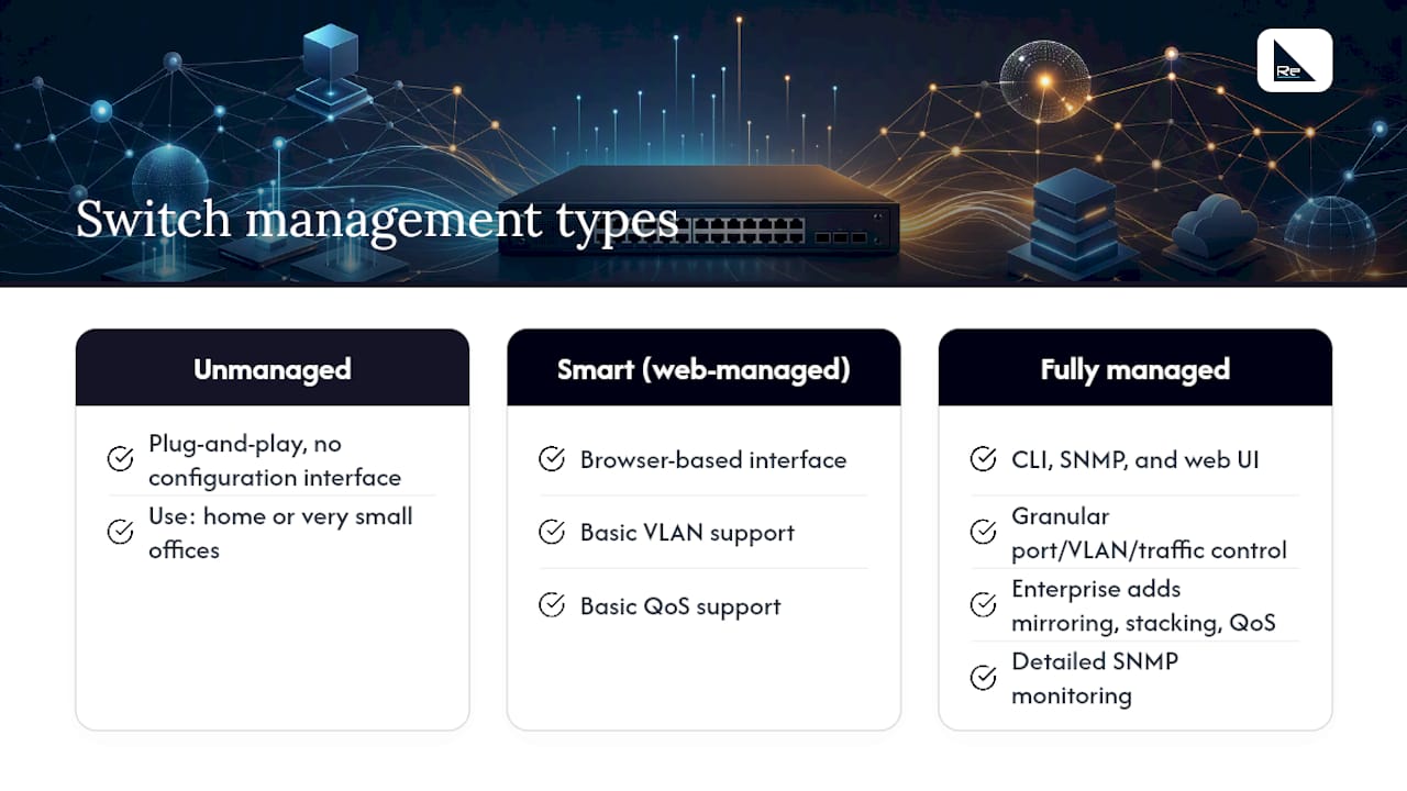
Enterprise managed switches add port mirroring, stacking, QoS, and detailed SNMP monitoring, features that are not optional in business-critical environments.
Layer 2 vs Layer 3
A Layer 2 switch forwards frames by MAC address within a single broadcast domain. A Layer 3 switch adds IP routing between VLANs, removing the need for a separate router for inter-VLAN traffic. In most small offices a Layer 2 switch with a router handles everything; in multi-VLAN campus networks a Layer 3 core switch is standard.
PoE
Power over Ethernet delivers DC power through the Ethernet cable to devices that lack a local power supply. Typical use cases include Wi-Fi access points, VoIP handsets, IP cameras, and door-entry controllers. PoE budgets are finite: a 24-port PoE switch cannot simultaneously power 24 devices that each draw more power than the switch’s total PoE budget allows. Always calculate total PoE draw before specifying hardware. The Zyxel XGS1930-52 managed L3 Gigabit PoE switch is one example of a managed PoE platform with L3 capabilities suited to small and mid-size deployments.
Form factors and port speeds
| Environment | Recommended type | Port count | Uplink speed | Management |
|---|---|---|---|---|
| Home / SOHO | Unmanaged desktop | 5 ports | 1G | None |
| Small office | Smart / web-managed | 24 ports | 1G | Web UI |
| Mid-size business | Fully managed Layer 2/3 | 24–48 ports | 10G SFP+ | CLI + SNMP |
| Campus / enterprise | Managed Layer 3, stackable | 48+ ports | — | Full suite |
- Desktop switches suit small workgroups; rack-mount units fit structured cabling environments.
- 10G uplinks are increasingly standard on 1G access switches to avoid bottlenecks at the aggregation layer.
- Stacking allows multiple physical switches to appear as one logical unit, simplifying management and improving resilience.
How VLANs segment your network traffic
A VLAN (Virtual Local Area Network) is a logical broadcast domain configured on a switch, independent of physical port location. Devices in VLAN 10 cannot communicate directly with devices in VLAN 20 without passing through a Layer 3 device, even if both VLANs share the same physical switch.
- Access ports carry traffic for a single VLAN. The switch adds no VLAN tag to frames leaving an access port, so the connected device is unaware of the VLAN.
- Trunk ports carry traffic for multiple VLANs simultaneously. Frames are tagged with an 802.1Q header identifying their VLAN, allowing switches and routers to sort them correctly.
- Guest Wi-Fi isolation is a common use case: the guest SSID maps to a dedicated VLAN, which trunks to the router and exits to the Internet without ever touching the corporate LAN. This is one of the most practical secure network design patterns for any organisation handling sensitive data.
- IGMP snooping prevents multicast streams (video surveillance feeds, for example) from flooding every port in a VLAN. The switch tracks IGMP membership reports and forwards multicast only to ports that have joined the relevant group.
VLANs reduce broadcast domain size, improve security, and simplify compliance segmentation, making them a standard feature in any managed switch deployment beyond the simplest home network.
How to connect a switch to a router correctly
- Power on the switch and confirm the power LED is solid (not blinking in an error pattern).
- Connect the uplink. Run an Ethernet cable from any switch port to a LAN port on the router. On managed switches, designate this as the uplink or use a dedicated uplink port if one exists.
- Connect end devices. Plug PCs, printers, access points, and servers into the remaining switch ports.
- Verify link LEDs. Each occupied port should show a solid or blinking green link/activity LED within a few seconds of connection.
- Configure a management IP (managed switches only). Assign the switch a static IP address on the management VLAN so it is reachable for configuration and monitoring. Keep this on a dedicated management VLAN where possible.
- Verify connectivity. Ping the default gateway from a connected device. Then ping between two devices on the same switch to confirm Layer 2 forwarding is working.
- Enable Spanning Tree Protocol (STP). If you are cascading multiple switches, STP prevents loops that would otherwise cause broadcast storms. Most managed switches enable STP by default; verify this before adding redundant uplinks.
For larger sites, network infrastructure planning should map out access, aggregation, and core layers before any cabling begins. In common deployments, switches are classified as edge/access, aggregation/distribution, and core; spine-leaf designs remove the aggregation layer to reduce latency in data centres.
How to tell if a network switch is working properly
Physical and logical checks together give a reliable picture of switch health.
Physical checks:
- Power LED solid green: switch is powered and operating normally.
- Per-port link LED solid: a physical connection exists. Blinking indicates activity. No LED means no link, which points to a cable, NIC, or port fault.
- PoE indicator: some switches show a PoE LED per port; if it is absent on a device that needs power, check the PoE budget and port configuration.
Basic diagnostic tests:
- Ping between two devices on the same switch. Failure here points to a Layer 2 issue (wrong VLAN, STP blocking, MAC table problem) rather than a routing issue.
- Inspect the MAC address table. A device’s MAC missing from the table means the switch has not received traffic from it; check the physical connection first.
- Use port mirroring or SNMP counters to capture traffic and identify errors, collisions, or excessive broadcasts.
Common failure signs:
- Broadcast storm / flooding: usually caused by a network loop where STP is disabled or misconfigured. Symptoms include all devices losing connectivity simultaneously and switch CPU spiking.
- High CPU on a managed switch: often indicates a misconfiguration, a spanning-tree topology change loop, or a denial-of-service condition.
- PoE devices not powering on: check total PoE draw against the switch’s rated budget; over-subscription is the most common cause.
When physical checks and basic pings do not resolve the issue, escalate to reviewing SNMP counters, syslog entries, and interface error statistics. Persistent issues in a business environment warrant a professional network audit to identify root causes systematically.
How to choose the right switch for your environment
Key questions to answer before specifying:
- How many wired ports do you need now, and in 18 months?
- What uplink speed does your aggregation or router port support?
- Which devices need PoE, and what is their combined power draw?
- Do you need VLANs, QoS, or 802.1X port authentication?
- Is redundancy (stacking, dual uplinks, STP) required for uptime SLAs?
- What warranty and support response time does the vendor offer?
Red flags to avoid:
- No VLAN support on a switch intended for a multi-tenant or multi-department environment.
- Uplink ports limited to 1G on a 48-port access switch (creates an immediate bottleneck).
- Unclear or shared PoE budget with no per-port power monitoring.
- No management interface for a switch serving business-critical devices.
For small offices, a smart-managed 24-port switch with a 10G uplink covers most scenarios. Mid-size businesses typically need fully managed Layer 2/3 switches with SNMP and CLI access. Enterprise deployments require stackable, redundant hardware with full monitoring, and benefit from network design best practices applied from the outset. The Ubiquiti UniFi managed L3 aggregation switch is one example of a mid-market managed platform with Layer 3 routing and aggregation capabilities.
When to choose a managed service and how Re-solution supports switch deployments
Some switch deployments are straightforward; others are not. Managed services become the right choice when:
- The network spans multiple buildings, floors, or sites with complex VLAN and segmentation requirements.
- Uptime SLAs are contractual and downtime carries financial or reputational consequences.
- Security or compliance obligations (such as DfE switching standards in education, or PCI DSS in retail) require documented configuration and audit trails.
- The internal team lacks the capacity to monitor, patch, and maintain switch firmware across a large estate.
Re-solution is a Cisco partner with over 35 years of experience deploying and managing network infrastructure across education, manufacturing, logistics, hospitality, and shared workspaces. Services include network audits, site surveys, Network as a Service (NaaS) subscriptions, and full managed services covering Cisco Catalyst and Cisco Meraki switching platforms.
A practical example: a multi-site further education college with a large number of connected devices required VLAN segmentation for student, staff, and guest traffic, alongside PoE infrastructure for a campus-wide wireless refresh. Re-solution delivered a structured audit, a phased Cisco Meraki deployment, and an ongoing NaaS contract, giving the college predictable costs and 24/7 monitoring without expanding its internal IT headcount.
If you are unsure whether your current switching infrastructure is fit for purpose, the logical next step is a professional audit. Re-solution’s network audit service identifies configuration gaps, capacity constraints, and security risks before they become outages.
Key takeaways
A network switch forwards frames within a LAN by learning MAC addresses at Layer 2, and managed switches extend that foundation with VLANs, PoE, and monitoring capabilities that are necessary for any business-critical deployment.
| Point | Details |
|---|---|
| Core switching function | Switches forward Ethernet frames by MAC address at OSI Layer 2, reducing unnecessary traffic compared with a hub. |
| MAC learning and ageing | The switch builds a MAC address table dynamically; entries expire after inactivity (commonly around 300 seconds) and are relearned on next contact. |
| VLANs and segmentation | VLANs create separate broadcast domains on a single switch, enabling traffic isolation for security and compliance without additional hardware. |
| Diagnostic starting point | Check power and link LEDs first, then ping across devices, then inspect the MAC address table to isolate Layer 2 faults. |
| Re-solution managed services | Re-solution offers Cisco-based audits, NaaS, and managed switching for organisations that need professional-grade deployment and ongoing support. |
Why visibility and segmentation matter more than port count
Most procurement conversations focus on port count and price. Those are the wrong starting points. The questions that actually determine whether a switched network performs well over time are: can you see what is happening on it, and can you control who talks to whom?
A switch with no management interface gives you neither. You cannot identify which port is generating a broadcast storm, which device is consuming the PoE budget, or whether a misconfigured VLAN is leaking traffic between departments. That invisibility is manageable in a home network. In a school, a warehouse, or a hotel with hundreds of connected devices, it is a liability.
The second underestimated factor is segmentation. VLANs are not an advanced feature reserved for large enterprises; they are the minimum viable security control for any network that mixes guest, operational, and sensitive traffic. A flat network where every device can reach every other device is not a network design choice, it is an absence of one.
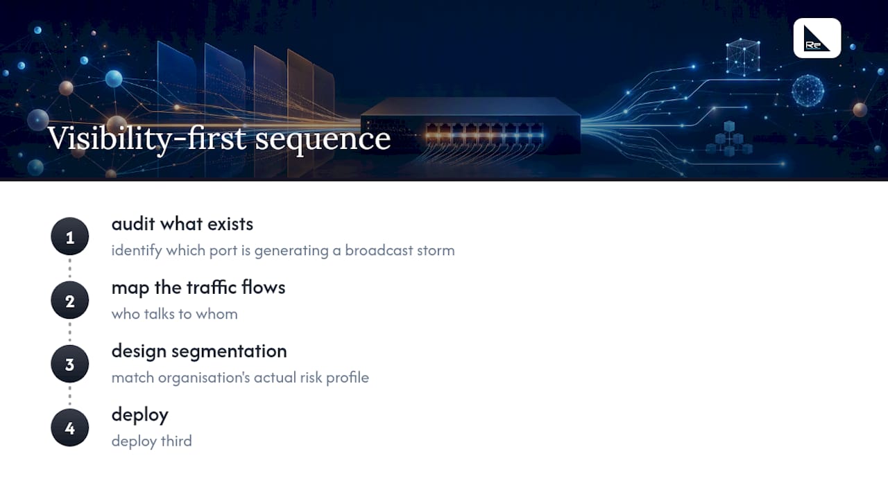
Re-solution’s approach, built on 35 years of Cisco infrastructure experience, starts with visibility: audit what exists, map the traffic flows, and then design segmentation that matches the organisation’s actual risk profile. That sequence, audit first, design second, deploy third, is what separates networks that stay healthy from those that require emergency intervention.
Re-solution: professional switch deployment and managed networking
Re-solution delivers Cisco-based network infrastructure services to organisations across the UK that need more than plug-and-play switching. Where a standard switch purchase ends at the hardware, Re-solution’s engagement begins with a structured network audit that maps your existing estate, identifies gaps, and produces a clear remediation plan.

For organisations that prefer a subscription model, Re-solution’s Network as a Service covers hardware, configuration, monitoring, and support under a single monthly cost, removing capital expenditure and the management burden from internal teams. As a Cisco partner, Re-solution deploys Catalyst and Meraki switching platforms with the configuration rigour and ongoing monitoring that business-critical networks require. Contact Re-solution to request a network audit or discuss a NaaS engagement for your organisation.
Useful sources and further reading
- Network switch — Wikipedia: a solid reference for the technical definition of switching, collision domains, and forwarding modes including cut-through and store-and-forward.
- What is a network switch and how does it work? — Network World: covers managed switch features, Layer 3 switching, and the internal LAN performance perspective.
- What is a Network Switch? How it Works and Types — TechTarget: useful for topology classifications (access, aggregation, core, spine-leaf) and the switch vs router distinction.
Recommended
- Network Solutions Explained: What You Should Know | Re-Solution
- Best Practices for Network Design Explained | Re-Solution