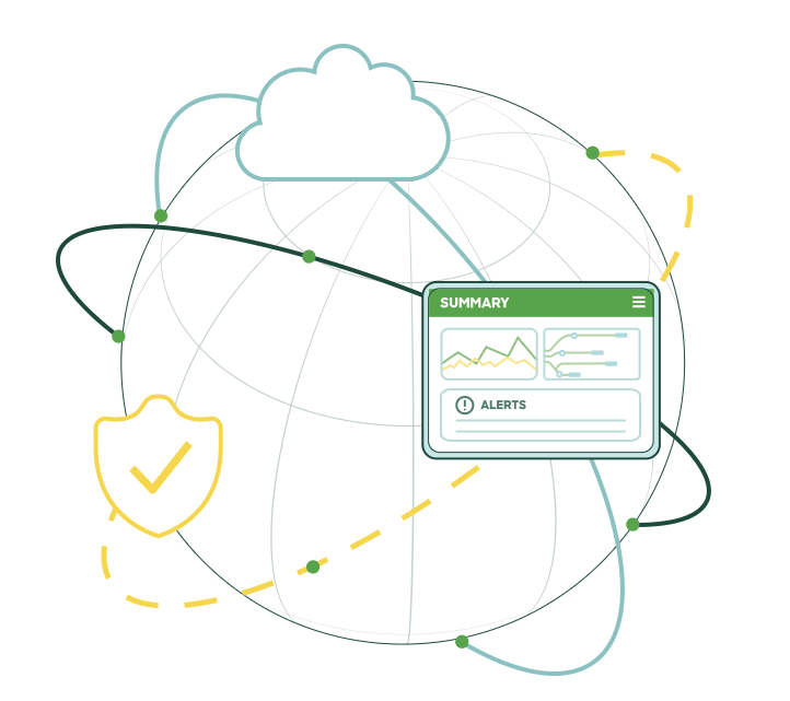
A successful Meraki Wi-Fi design comes down to five aligned decisions: access point density, channel plan, SSID and security policy, a verified site survey, and post-deployment tuning through the Dashboard. Get those right and the network performs predictably under load. The sections below cover the numbers, the configuration settings and the survey methods that engineers use to make each decision correctly, using Meraki Dashboard tools and professional survey platforms such as Ekahau and Fluke Networks AirMagnet.
TL;DR:
- Use a site survey tool before and after deployment to validate coverage, channel plans, and 6 GHz readiness, avoiding coverage gaps or interference issues.
- Limit Wi-Fi to around three SSIDs per access point and enable band steering to reduce airtime consumption and improve overall throughput.
- Plan for one access point per 110 to 185 square meters in open-plan offices, spacing APs roughly 12 meters apart, and adjust minimum bitrate settings carefully through testing.
- Prioritize 5 GHz and 6 GHz bands for capacity, and reserve 2.4 GHz for legacy or low-power IoT devices, using narrow channel widths in high-density areas.
- Continuously monitor the network through the Dashboard, checking for rogue SSIDs and interference, and constrain AutoRF to preferred settings validated during surveys.
Table of Contents
- Practical Meraki Wi-Fi design checklist
- RF design and cell planning: AP density, spacing and minimum bitrates
- Channel planning and interference control
- SSID architecture and security: limits, band steering and 6 GHz
- Site surveys and validation: predictive, active and Meraki survey mode
- High-density tuning and capacity planning
- Operational best practices: Dashboard, monitoring and post-deployment checks
- Re-Solution proof points and services that implement the guide
- Practitioner perspective: when to deviate from textbook rules
- How Re-Solution can help
- Authoritative Meraki documents and recommended survey tools
- Sources
- FAQ
Practical Meraki Wi-Fi design checklist
Before opening the Dashboard, an engineer needs a clear picture of what the network has to support. Skipping requirements gathering is the single most common cause of a redesign six months after go-live.
- Collect requirements: client counts per zone, application mix (voice, video, IoT, guest), roaming domains and the purpose of each SSID.
- Map VLANs and roaming domains to Meraki Networks, so Layer 2 boundaries match the physical areas where clients actually move.
- Limit the number of SSIDs and use Group Policy to differentiate access levels instead of creating a new SSID for every use case.
- Run a predictive survey first, then validate with an active or passive survey once hardware is on site, then tune again after deployment.
- Set Dashboard basics early: RF profiles, constrained AutoRF ranges, minimum bitrates and SSID visibility per AP or AP tag.
Each of these steps feeds the next. A roaming domain that spans two VLANs will break voice calls regardless of how well the RF is tuned, and an SSID count of six will erode airtime no matter how carefully the channels are planned. The checklist works because it forces requirements and architecture decisions before anyone touches transmit power.
RF design and cell planning: AP density, spacing and minimum bitrates
Cell size is the variable that determines almost everything else in a Meraki deployment: capacity, roaming behaviour and channel reuse all follow from it. Meraki’s own architecture guidance gives engineers a starting point rather than a fixed rule.
- Plan for one access point per 110 to 185 square metres in typical open-plan office environments, according to Meraki’s RF design guidance.
- Space APs roughly a dozen metres or so apart on a standard office ceiling to keep cell edges overlapping enough for clean roaming without excessive co-channel contention.
- Set RX-SOP (receiver start of packet) at a baseline near -78 dBm, which controls the point at which an AP treats a signal as usable and effectively sets the cell boundary.
- Treat minimum bitrate as a cell-size lever: raising it shrinks the cell by forcing clients to associate closer to the AP, which increases density-adjusted throughput but can also strand older or low-power devices.
One planning constant worth memorising: Meraki recommends 110–185 m² per AP and 12–15 m spacing for enterprise open-office layouts, a figure that anchors most predictive designs before a single survey point is taken, per Meraki’s enterprise best-practice documentation.
Raising RX-SOP or minimum bitrate to shrink cells is a legitimate tactic in dense deployments, but it needs testing before a global rollout. A setting that looks correct on paper can leave a coverage gap at a lift lobby or a firewall stairwell if it is pushed to every AP without checking cell-edge behaviour on the client hardware actually in use. The safest iteration loop is: adjust one RF profile, apply it to a small AP tag, walk the edge of the intended cell with a real device, then expand once it holds up. Trying to fix coverage holes by adding APs before checking whether the existing layout has a bitrate or RX-SOP mismatch usually wastes hardware budget without solving the underlying problem.
Channel planning and interference control
Channel selection determines how much of that carefully planned cell size actually translates into usable throughput. Co-channel interference from a neighbouring AP, whether Meraki’s own or a rogue device, eats into airtime just as effectively as a badly placed access point.
- Favour 5 GHz and 6 GHz for capacity-carrying traffic; keep 2.4 GHz active only where legacy or low-power IoT devices require it, since its limited channel count makes it the first band to run out of clean spectrum.
- Use 20 MHz channel width in congested or high-density areas to maximise the number of non-overlapping channels available. This setting is recommended by Meraki specifically for high-density Wi-Fi deployments.
- Reserve 40 MHz or 80 MHz channels for less crowded zones such as warehouses or low-density office wings, where fewer APs compete for the same spectrum.
- Understand DFS (Dynamic Frequency Selection) behaviour on 5 GHz DFS channels: radar detection can force an AP to vacate a channel with little warning, which is disruptive in latency-sensitive environments and one reason engineers avoid DFS-heavy channel plans for voice or video zones.
- Let AutoRF handle day-to-day adjustment, but expect to override it with manual channel and power assignment once survey data shows persistent co-channel contention. Meraki’s own channel planning guidance notes that automation is not always aggressive enough for genuinely high-density sites.
The practical rule is to let automation run the network most of the time and reserve manual tuning for the specific floors or zones where survey data shows a recurring problem, rather than manually fixing every AP on day one.
SSID architecture and security: limits, band steering and 6 GHz
Every SSID broadcast on an AP consumes airtime for beacons and management traffic, whether or not a client is connected to it. That cost is invisible until a site has six SSIDs and wonders why throughput sags at peak occupancy.
- Keep active SSIDs to around three per AP, as Meraki’s architecture guidance recommends, and use Group Policy to differentiate staff, guest and IoT access on the same broadcast rather than adding a new SSID for each.
- Set per-AP or per-tag SSID availability for genuine exceptions, such as a guest SSID that only needs to broadcast in reception and communal areas, as demonstrated in this guest Wi-Fi case study.
- Enable band steering so dual-band clients default to 5 GHz or 6 GHz, and disable legacy bit rates to stop older, low-rate transmissions from holding the channel longer than necessary.
- On 6 GHz, WPA3 and Protected Management Frames are mandatory. Identity PSK (IPSK) is useful where a single SSID needs to issue distinct pre-shared keys per device or group without deploying full 802.1X.
- Configure Air Marshal to classify rogue and neighbouring SSIDs and to contain genuine threats automatically, using the dedicated scanning radio built into current MR access points for continuous spectrum visibility.
Pro Tip: Audit SSID count before touching RF settings: consolidating from six SSIDs to three often improves perceived performance more than any channel or power change.
Site surveys and validation: predictive, active and Meraki survey mode
No amount of desk-based planning replaces a survey against the actual building. Meraki’s guidance on conducting site surveys with MR access points sets out a sequence engineers should follow rather than skip.
- Run a predictive survey before hardware arrives, using floor plans and building materials in tools like Ekahau or Fluke Networks AirMagnet to model expected coverage and identify problem zones early. A predictive Wi-Fi survey at this stage avoids the six to ten decibel surprises that generic assumptions about wall attenuation tend to produce.
- Once APs are mounted, run an active or passive survey with the exact AP model that will be deployed, walking the site to confirm real signal strength, SNR and channel behaviour against the predictive model.
- Use Meraki’s own site-survey mode, which broadcasts a dedicated survey SSID and exposes local RF and spectrum metrics directly from the AP, to cross-check readings without needing a laptop tethered to a survey tool.
- Target voice-grade design points during validation: a cell edge near -67 dBm and an SNR close to 25 dB, thresholds Meraki cites for reliable voice and video performance.
- For 6 GHz Standard Power planning, run GNSS validation in site-survey mode, aiming for at least eight satellites in view and a minimum of four anchor APs per floor so the Automated Frequency Coordination system has enough data to clear higher power levels.
Iterating between these tools, rather than relying on any single one, is what separates a design that survives contact with a real building from one that only ever existed on a floor plan. A wireless site survey that skips the active on-site pass is a prediction, not a validation.
High-density tuning and capacity planning
Lecture theatres, auditoria and open-plan trading floors need a different starting point from a standard office, because the constraint shifts from coverage to simultaneous client capacity. The RF profile has to shrink cell size deliberately, even where raw coverage would be fine with fewer APs.
| Space type | AP density guidance | Channel width | Typical minimum bitrate approach |
|---|---|---|---|
| Open-plan office | 110-185 m² per AP | 20 MHz | Moderate, tuned to device mix |
| Lecture theatre or auditorium | Higher AP count per seating block | 20 MHz | Raised, to force smaller cells |
| Warehouse or low-density floor | Wider spacing where headroom allows | 40/80 MHz | Standard, coverage-led |
In a lecture theatre, the client count in a single room can exceed what one AP handles cleanly, so the design leans on smaller cells and 20 MHz channels to maximise the number of usable channels in a tight space, following the high-density deployment guidance Meraki publishes for these environments. Disabling 2.4 GHz selectively in the densest rooms, combined with band steering, pushes capable clients onto the less congested bands. The dedicated scanning radio on current MR hardware continues monitoring spectrum in the background, which matters in these spaces because interference sources change as the room fills and empties between sessions.
Operational best practices: Dashboard, monitoring and post-deployment checks
Design work does not end at go-live. The Dashboard gives engineers the visibility to confirm the RF plan is holding up once real clients, real interference sources and real usage patterns arrive.
- Check the Air Marshal view regularly for rogue and neighbouring SSIDs, and review the Interfering APs list to spot co-channel or adjacent-channel problems that were not visible during the survey window.
- Use the channel utilisation graphs and per-AP local status pages to confirm that channel width and power settings are behaving as configured, rather than assuming AutoRF has converged correctly.
- Keep AutoRF enabled but constrain its channel and power ranges to the values validated during the survey, so automation cannot drift outside the tested plan.
- Automate recurring checks with the Meraki API, scheduling pulls of client counts, channel utilisation and AP health so drift gets flagged before users notice it.
A network that passed its survey a month ago can still degrade as furniture moves, new equipment arrives, or a neighbouring tenant installs their own access points. Treating the Dashboard as an ongoing monitoring tool, not a one-time configuration screen, is what keeps the original design intact.
Re-Solution proof points and services that implement the guide
The company has extensive experience as a Cisco partner, applying that expertise specifically to wireless survey and deployment work. The services that put this guide into practice include wireless surveys using professional predictive and active survey methods, network audits that benchmark an existing estate against best practice, managed services for ongoing Dashboard monitoring, and subscription-based network offerings. A multi-site Meraki deployment case study illustrates how these pieces come together across a real estate. This article was written by Jacob, drawing on that same body of deployment experience.

Practitioner perspective: when to deviate from textbook rules
Standard spacing and channel guidance assumes fairly typical construction. Glass atriums, deep concrete interiors and dense metal racking all behave differently, and applying textbook density figures in those spaces produces either dead zones or wasted hardware. The reliable approach is still predictive, then active, then post-deployment verification, repeated rather than skipped. Document the assumptions behind every RF profile and expected client count: six months later, nobody remembers why a room was set to raised minimum bitrate, and that context is what saves the next redesign.
— Jacob
How Re-Solution can help
Reading the guidance is one thing; validating it against a specific building, client density and roaming pattern is another, and that is where a professional survey earns its cost back quickly. Re-Solution runs the same predictive-to-active-to-post-deployment loop described above as a structured service, using Ekahau and Fluke Networks AirMagnet alongside Meraki’s own site-survey mode and GNSS validation.
- Wireless Surveys: predictive and on-site validation to confirm AP placement, channel plan and 6 GHz readiness before or after installation, detailed on the Wireless Surveys service page.
- Network Audits: a benchmark of an existing wireless estate against the density, channel and SSID practices covered in this guide, via Network Audits.
- Managed Services and Network as a Service: ongoing Dashboard monitoring and RF tuning once the network is live, through Managed Services or Network as a Service.
If a deployment is due for its first proof-of-performance check or a predictive survey ahead of a refit, the Wireless Surveys page is the right place to start a conversation.
Authoritative Meraki documents and recommended survey tools

This guide draws on Meraki’s published RF design, architecture, channel planning and GNSS validation documentation, alongside professional survey platforms Ekahau and Fluke Networks AirMagnet.
FAQ
How do I configure Meraki Wi-Fi?
Start in the Dashboard by creating SSIDs limited to around three per AP, applying Group Policy for access differentiation, and setting RF profiles with constrained AutoRF ranges rather than fully open automation. Follow that with a predictive survey, an active on-site survey using the deployed AP model, and a post-deployment check before considering the configuration final.
Is Meraki MDM going away?
Meraki’s mobile device management capability, Systems Manager, remains part of the Meraki product line and is not documented as being discontinued. Any change to a specific product’s roadmap is confirmed through Cisco Meraki’s own release documentation rather than general guidance.
Is Meraki discontinued?
No, Cisco Meraki continues to be an actively developed and sold product line, including the MR wireless access points covered throughout this guide. Specific hardware models do reach end-of-sale and end-of-support dates over time, which is normal lifecycle management rather than discontinuation of the platform.
Is Meraki a router or a firewall?
Meraki’s MX line functions as a security appliance combining firewall, SD-WAN and routing capabilities, while the MR line covered in this guide is purpose-built wireless access point hardware. The two product families are managed through the same Dashboard but serve different roles in the network.
Recommended
- Wireless Aruba for IT directors: a decision-maker’s guide
- Optimise Wi-Fi bandwidth: A practical management guide
- Simplify Wi-Fi with Cisco Meraki Go
- Meraki Access Control vs Cisco ISE